

Docs Menu
Network Model Import and Validation
Import an electrical case, resolve source and topology issues, and check readiness before running a study.
Watch the Video: Grid Circuit Builder & Model Import (1:06)
Choose the Input Path
| Input | Where to use it | What it means |
|---|---|---|
| Current map layers | Setup & Run | Capture a map scope or selected assets, then review how the layers map to electrical roles. |
| Displayed single-line diagram | Import > Current Single-Line Diagram in Grid Circuit Builder | Create an unsaved circuit draft from the displayed nodes and links. Preserve source limits and review inferred relationships. |
| RAW or RAWX electrical case | Import PSS/E in Grid Circuit Builder | Preview the file set, then create a circuit with a stored revision. |
| Published circuit revision | Setup & Run | Use a specific validated published revision without recapturing map features. |
Engineering Studies requires Professional or Enterprise access. Circuit imports also require an engineering project and an owner or editor role.
Import RAW or RAWX Files
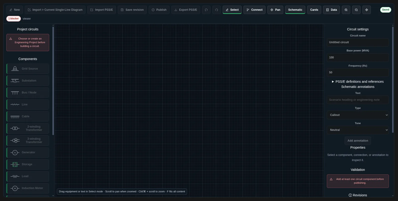
- Open Grid Circuit Builder and select the project.
- Save any current draft changes.
- Select Import PSS/E.
- Select the case file and its optional companion files.
- Review Circuit file import preview.
- Check the detected format, version, source-file count, equipment counts, diagnostics, unsupported sections, and attachments.
- Enter Circuit name.
- Select Create circuit, or Cancel to leave the preview.
| File | Accepted purpose |
|---|---|
.raw | Text case in version 35 or 36. |
.rawx | JSON case in version 35 or 36. |
.seq | Sequence data. Supported records are mapped; unsupported or unresolved records are reported. |
.con | Contingency definitions. |
.mon | Monitor definitions. |
.sub | Subsystem definitions. |
.dyr | Preserved dynamic-model attachment. Preservation does not mean dynamic models are simulated or validated by the circuit importer. |
Provide one RAW case, one RAWX case, or one compatible RAW/RAWX pair. A pair must use the same version and describe the same mapped electrical network. Each companion type can appear only once. Use distinct filenames. Binary SAV files are not supported.
Unsupported sections can remain preserved for round-trip evidence without being electrically mapped. Read their diagnostics before treating the imported case as complete. An error for an unmapped electrical section still needs correction; preserving its source text does not resolve it. File acceptance does not publish the circuit or prove that a study engine can use every imported section.
Reconcile a Map Diagram Import
For the capture and preview procedure, see Single-Line Diagrams and Engineering. In the imported circuit, use Import reconciliation to resolve each issue.
| Issue or control | Required action |
|---|---|
| Incomplete or capped scope | Capture a more complete local scope, or enter an Acknowledgement reason and select Accept narrowed scope when the reduced scope is intentional. The reason remains attached. |
| Missing, duplicate, stale, or mismatched source reference | Check the original asset and recapture if needed. Use Detach as user-created only when you accept responsibility for maintaining the item independently of that source. |
| Unmapped component | Select the item and choose its explicit Equipment type. Review the fields and connections after changing the type. |
| Inferred connection | Select the link. Inspect its origin, method, confidence, and endpoint IDs. Use Confirm inferred link only after review, or use Remove link and reconnect it correctly. |
| Provisional equipment terminals | Connect a distinct bus to each terminal. Use Confirm endpoints when the sides are correct. Use Swap terminal sides for two-terminal equipment, then confirm the revised assignment. |
| Omitted link candidate | Use Acknowledge omitted candidate only after checking that it is not an electrical connection in this circuit. |
| More issues below the visible list | Use Show … more issues (… remaining). The button displays the next issue count and remaining total. |
| Suggested electrical value | Check the source, then edit the property to confirm the intended value. Supply missing required values. |
An unresolved issue still needs action. accepted-narrow-scope records an explicit scope limitation and reason. recaptured-complete marks a resolved reconciliation item. Review the recorded reason and scope for each reconciliation item.
Resolve Circuit Validation
The builder checks required values, numeric ranges, unique IDs, equipment mappings, source identities, terminals, inferred-link review, and unresolved scope issues. It also checks that each electrical island has a grid source.
- Supply positive base power, frequency, bus voltages, and required ratings.
- Provide line and transformer impedances. Do not use zero for both R and X.
- Keep operating P and Q within the limits you supply.
- Check tap limits and the supporting control fields for non-neutral taps or voltage control.
- Match transformer terminal sides to bus voltages. The check uses the greater of 2% or 0.1 kV as its voltage tolerance.
- Confirm terminal assignments again if you change their connected buses.
- Review disconnected-equipment warnings.
See Grid Circuit Element Reference for type-specific fields. A draft can be saved before it is valid. Publication requires the current saved revision to pass blocking checks.
Review Map-Layer Mapping
- In Setup & Run, select the intended scope, study type, and engine.
- Select Refresh Scope after changing the map or asset selection.
- Read captured-feature and skipped-feature information. Check any feature-cap warning.
- In Mapping Review, keep Auto detect or assign the correct role to each displayed input layer.
- Select Check Readiness.
The role choices are Bus / point, Branch / feeder, Transformer, Load, Generator / DER, Storage, and Switch. A role override changes model conversion. It does not add missing electrical fields to the source layer.
Use Add Inputs to Map to show a frozen copy of mapped inputs. If the mapped inputs change, use Update Inputs on Map. Inputs Added to Map marks the current overlay. Remove Inputs removes that overlay without deleting the source data.
Use a Published Circuit Revision
- Select the project in Session Context.
- Open Setup & Run and choose the study type and engine.
- Select Circuit Revision.
- Choose Published circuit revision and wait for its model to load.
- Select Check Readiness and review the returned diagnostics.
This input path supports model quality, power flow, contingency analysis, sensitivity analysis, PTDF/LODF, and cross-check studies. Other study types need their supported input path. Later circuit edits do not change the selected revision.
Read Model Readiness
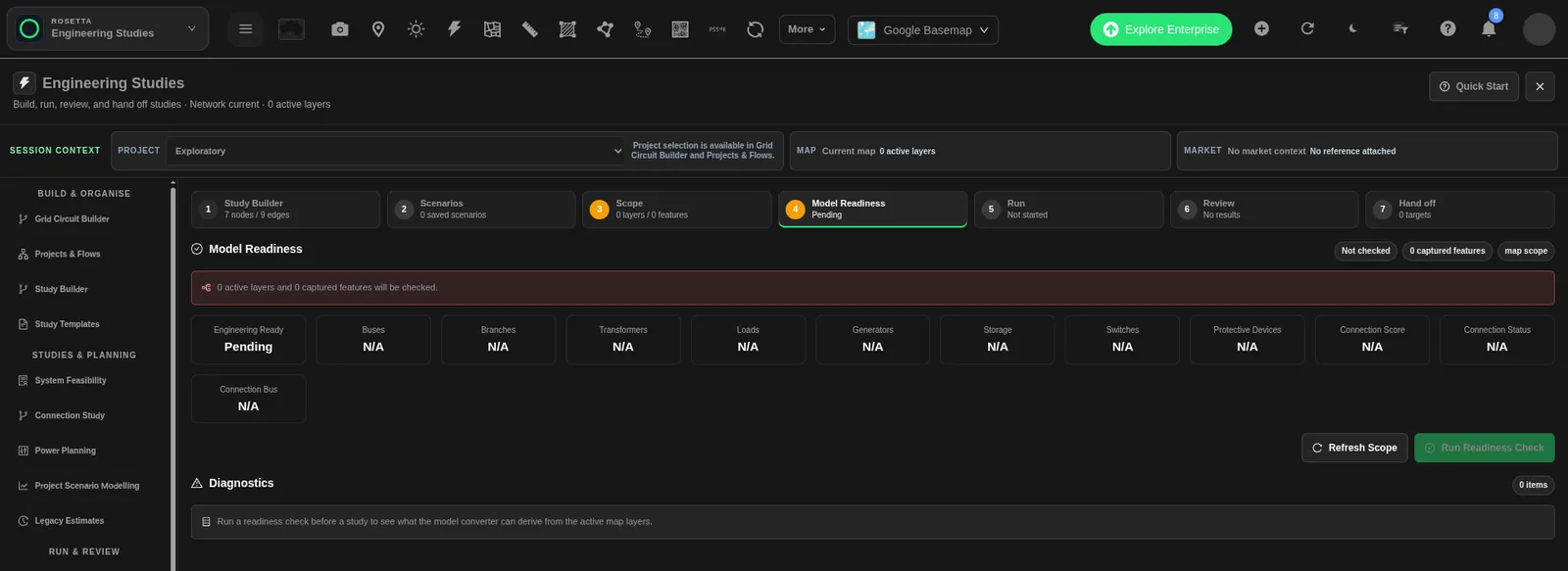
Model Readiness shows the checked scope and equipment counts for buses, branches, transformers, loads, generators, storage, switches, and protective devices. It can also show Connection Score, Connection Status, and Connection Bus when the response provides them.
| Status | Meaning and next step |
|---|---|
| Not checked / Pending | No readiness result is available. Select Run Readiness Check. |
| Checking | The model check is in progress. Wait for the result. |
| Ready / Engineering Ready = Yes | The returned model passes the engineering-readiness gate. Read diagnostics before running the selected study. |
| Needs work / Engineering Ready = No | The model needs corrections. Use the diagnostics to fix input data or scope, then rerun the check. |
| error | Correct the reported problem before relying on the affected model or study. |
| warning | Review the reported limitation or assumption. Decide whether the study scope remains suitable. |
| info | Read the supporting detail and preserve it with the study basis. |
| N/A | The value was not supplied or is not applicable. It is not a measured zero or a pass. |
Diagnostics lists each code, severity, message, and related element ID when available. Correct the underlying input, then select Run Readiness Check again. A check without a required limit is not assessed. An absent limit must not be treated as unlimited capacity.
Review the Dynamic Source Inputs
A static model import is not proof that a dynamic model is valid. For generated PSS/E dynamic cases, review each in-service generator's explicit source resistance and reactance on its machine MVA base and supply suitable authorized plant dynamics. The stock single-machine harness does not provide a plant dynamic model.
Check attachment identity and compatibility after model changes. Read the handoff guidance before using the case in a licensed solver.
Related Guides
- Grid Circuit Builder
- Grid Circuit Element Reference
- Single-Line Diagrams and Engineering
- Running Engineering Studies
- Engineering Exports and Handoffs


