

Docs Menu
Grid Circuit Element Reference
Use this reference to enter equipment properties and check the defaults in a new Grid Circuit Builder component.
How to Use the Fields
- Select equipment in Grid Circuit Builder.
- Set Name and check Equipment type.
- Enter the normal properties.
- Select Show advanced and sequence fields to expose fields marked Advanced below.
- Review Validation, then save a revision.
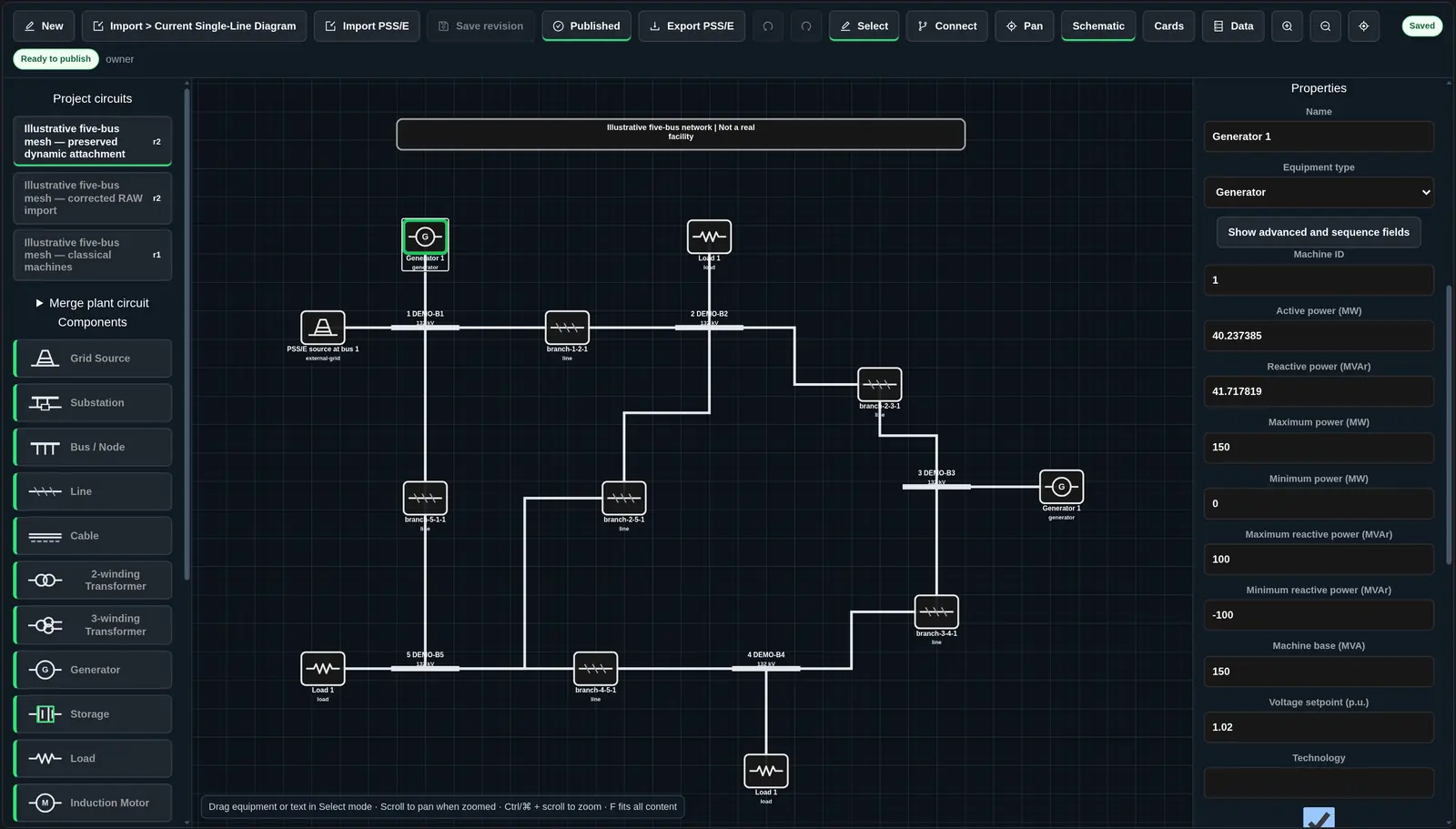
Units are part of each field label. Values shown under Default use those units. “Blank” means no value is supplied. A new-component default is an editable starting value, not verified asset data. Imported data can have different values and review requirements.
Use a finite number for numeric fields. Do not put unit text in a numeric input. Select fields use the choices shown below. Checkbox defaults are shown as selected or cleared. In service controls equipment availability where the field is present. Minima must not exceed maxima.
Grid Source
Connect to one bus. The voltage setpoint and angle define the reference source. Fault and sequence fields support studies that need source strength. Leave unknown fault values blank until you have verified data.
| Field | Input or choices | Default | Display |
|---|---|---|---|
| Voltage setpoint (p.u.) | Number | 1 | Standard |
| Angle (degrees) | Number | 0 | Standard |
| Legacy source fault level (MVA) | Number | Blank | Standard |
| Maximum fault level (MVA) | Number | Blank | Standard |
| Minimum fault level (MVA) | Number | Blank | Standard |
| Maximum-case R/X ratio | Number | Blank | Advanced |
| Minimum-case R/X ratio | Number | Blank | Advanced |
| Maximum-case X0/X1 ratio | Number | Blank | Advanced |
| Maximum-case R0/X0 ratio | Number | Blank | Advanced |
| Minimum-case X0/X1 ratio | Number | Blank | Advanced |
| Minimum-case R0/X0 ratio | Number | Blank | Advanced |
| Slack participation factor | Number | Blank | Advanced |
| In service | Checkbox | Selected | Standard |
Substation and Bus / Node
Enter a positive nominal voltage. Both types use this same field set. The bus types are PQ, PV, Swing, and Isolated. A bus or substation can connect to several equipment terminals. Each equipment terminal connects only once. The model must have a grid source for each connected island.
| Field | Input or choices | Default | Display |
|---|---|---|---|
| Nominal voltage (kV) | Number | Blank | Standard |
| PSS/E bus number | Number | Blank | Standard |
| Bus type | PQ; PV; Swing; Isolated | PQ | Standard |
| Area number | Number | Blank | Standard |
| Zone number | Number | Blank | Standard |
| Owner number | Number | Blank | Standard |
| Initial voltage (p.u.) | Number | Blank | Standard |
| Initial angle (degrees) | Number | Blank | Standard |
| Minimum voltage (p.u.) | Number | 0.95 | Standard |
| Maximum voltage (p.u.) | Number | 1.05 | Standard |
| Emergency minimum voltage (p.u.) | Number | Blank | Advanced |
| Emergency maximum voltage (p.u.) | Number | Blank | Advanced |
Line and Cable
Enter R, X, and a positive normal rating. R can be zero; R and X cannot both be zero. Impedances here are total ohms for the element, not ohms per kilometer. The length field is in kilometers. Connect one distinct bus to each end.
| Field | Input or choices | Default | Display |
|---|---|---|---|
| Nominal voltage (kV) | Number | Blank | Standard |
| Length (km) | Number | Blank | Standard |
| Positive-sequence R (ohm) | Number | Blank | Standard |
| Positive-sequence X (ohm) | Number | Blank | Standard |
| Positive-sequence B (S) | Number | Blank | Standard |
| Normal rating (MVA) | Number | Blank | Standard |
| RATE A (MVA) | Number | Blank | Standard |
| RATE B (MVA) | Number | Blank | Standard |
| RATE C (MVA) | Number | Blank | Standard |
| Circuit ID | Text | 1 | Standard |
| In service | Checkbox | Selected | Standard |
| Negative-sequence R2 (ohm) | Number | Blank | Advanced |
| Negative-sequence X2 (ohm) | Number | Blank | Advanced |
| Negative-sequence B2 (S) | Number | Blank | Advanced |
| Zero-sequence R0 (ohm) | Number | Blank | Advanced |
| Zero-sequence X0 (ohm) | Number | Blank | Advanced |
| Zero-sequence B0 (S) | Number | Blank | Advanced |
| From-end conductance (S) | Number | Blank | Advanced |
| From-end susceptance (S) | Number | Blank | Advanced |
| To-end conductance (S) | Number | Blank | Advanced |
| To-end susceptance (S) | Number | Blank | Advanced |
2-winding Transformer
Enter rating, high-side voltage, low-side voltage, R, and X. The high-side voltage must exceed the low-side voltage. R and X cannot both be zero. A non-neutral tap or voltage control also requires the tap side, neutral position, minimum and maximum positions, and step size. Match each winding to the correct bus voltage.
| Field | Input or choices | Default | Display |
|---|---|---|---|
| Rating (MVA) | Number | Blank | Standard |
| High-side voltage (kV) | Number | Blank | Standard |
| Low-side voltage (kV) | Number | Blank | Standard |
| Positive-sequence R (p.u.) | Number | Blank | Standard |
| Positive-sequence X (p.u.) | Number | Blank | Standard |
| RATE A (MVA) | Number | Blank | Standard |
| RATE B (MVA) | Number | Blank | Standard |
| RATE C (MVA) | Number | Blank | Standard |
| Tap ratio | Number | 1 | Standard |
| Tap side | HV; LV | HV | Standard |
| Neutral tap position | Number | Blank | Advanced |
| Minimum tap position | Number | Blank | Advanced |
| Maximum tap position | Number | Blank | Advanced |
| Tap step (%) | Number | Blank | Advanced |
| Phase shift (degrees) | Number | 0 | Standard |
| Control mode | Fixed; Voltage | Fixed | Advanced |
| Control target | Number | Blank | Advanced |
| Control deadband | Number | Blank | Advanced |
| Regulated bus | Text | Blank | Advanced |
| Vector group | Text | Blank | Advanced |
| HV grounding | Text | Blank | Advanced |
| LV grounding | Text | Blank | Advanced |
| Zero-sequence R0 (p.u.) | Number | Blank | Advanced |
| Zero-sequence X0 (p.u.) | Number | Blank | Advanced |
| Zero-sequence magnetizing impedance (%) | Number | Blank | Advanced |
| Zero-sequence magnetizing R/X ratio | Number | Blank | Advanced |
| HV share of zero-sequence impedance | Number | Blank | Advanced |
| Impedance base (MVA) | Number | Blank | Advanced |
| Magnetizing conductance (p.u.) | Number | Blank | Advanced |
| Magnetizing susceptance (p.u.) | Number | Blank | Advanced |
| Circuit ID | Text | 1 | Standard |
| In service | Checkbox | Selected | Standard |
3-winding Transformer
Enter all three winding voltages and ratings. Enter R, X, and an MVA base for each winding pair. HV voltage must be at least MV voltage, and MV must be at least LV voltage. Each winding needs a different bus. Tap controls need the same supporting tap fields as a two-winding transformer.
| Field | Input or choices | Default | Display |
|---|---|---|---|
| HV voltage (kV) | Number | Blank | Standard |
| MV voltage (kV) | Number | Blank | Standard |
| LV voltage (kV) | Number | Blank | Standard |
| HV rating (MVA) | Number | Blank | Standard |
| MV rating (MVA) | Number | Blank | Standard |
| LV rating (MVA) | Number | Blank | Standard |
| HV-MV R (p.u.) | Number | Blank | Standard |
| HV-MV X (p.u.) | Number | Blank | Standard |
| HV-MV base (MVA) | Number | Blank | Standard |
| MV-LV R (p.u.) | Number | Blank | Standard |
| MV-LV X (p.u.) | Number | Blank | Standard |
| MV-LV base (MVA) | Number | Blank | Standard |
| HV-LV R (p.u.) | Number | Blank | Standard |
| HV-LV X (p.u.) | Number | Blank | Standard |
| HV-LV base (MVA) | Number | Blank | Standard |
| Tap side | HV; MV; LV | HV | Standard |
| Tap ratio | Number | 1 | Standard |
| Neutral tap position | Number | Blank | Advanced |
| Minimum tap position | Number | Blank | Advanced |
| Maximum tap position | Number | Blank | Advanced |
| Tap step (%) | Number | Blank | Advanced |
| HV phase shift (degrees) | Number | 0 | Advanced |
| MV phase shift (degrees) | Number | 0 | Advanced |
| LV phase shift (degrees) | Number | 0 | Advanced |
| Control mode | Fixed; Voltage | Fixed | Advanced |
| Control target | Number | Blank | Advanced |
| Control deadband | Number | Blank | Advanced |
| Regulated bus | Text | Blank | Advanced |
| Vector group | Text | Blank | Advanced |
| HV grounding | Text | Blank | Advanced |
| MV grounding | Text | Blank | Advanced |
| LV grounding | Text | Blank | Advanced |
| HV-MV zero-sequence R0 (p.u.) | Number | Blank | Advanced |
| HV-MV zero-sequence X0 (p.u.) | Number | Blank | Advanced |
| MV-LV zero-sequence R0 (p.u.) | Number | Blank | Advanced |
| MV-LV zero-sequence X0 (p.u.) | Number | Blank | Advanced |
| HV-LV zero-sequence R0 (p.u.) | Number | Blank | Advanced |
| HV-LV zero-sequence X0 (p.u.) | Number | Blank | Advanced |
| Circuit ID | Text | 1 | Standard |
| In service | Checkbox | Selected | Standard |
Generator
Enter a positive maximum power. Keep active and reactive operating values inside the limits you supply. Sequence and grounding fields describe short-circuit behavior; the available study engine determines which fields it can use.
| Field | Input or choices | Default | Display |
|---|---|---|---|
| Machine ID | Text | 1 | Standard |
| Active power (MW) | Number | 0 | Standard |
| Reactive power (MVAr) | Number | 0 | Standard |
| Maximum power (MW) | Number | Blank | Standard |
| Minimum power (MW) | Number | 0 | Standard |
| Maximum reactive power (MVAr) | Number | Blank | Standard |
| Minimum reactive power (MVAr) | Number | Blank | Standard |
| Machine base (MVA) | Number | Blank | Standard |
| Voltage setpoint (p.u.) | Number | Blank | Standard |
| Remote regulated bus | Text | Blank | Advanced |
| Dispatch participation factor | Number | Blank | Advanced |
| Linear cost (/MWh) | Number | Blank | Advanced |
| Constant cost | Number | Blank | Advanced |
| Positive-sequence R1 (p.u.) | Number | Blank | Advanced |
| Subtransient X1 (p.u.) | Number | Blank | Advanced |
| Negative-sequence R2 (p.u.) | Number | Blank | Advanced |
| Negative-sequence X2 (p.u.) | Number | Blank | Advanced |
| Zero-sequence R0 (p.u.) | Number | Blank | Advanced |
| Zero-sequence X0 (p.u.) | Number | Blank | Advanced |
| Grounding R0 (p.u.) | Number | Blank | Advanced |
| Grounding X0 (p.u.) | Number | Blank | Advanced |
| Short-circuit current ratio | Number | Blank | Advanced |
| Owner number | Number | Blank | Advanced |
| Technology | Text | Blank | Standard |
| Dispatch controllable | Checkbox | Selected | Advanced |
| In service | Checkbox | Selected | Standard |
Storage
Enter base injection and positive energy capacity. Positive base injection means discharge; negative means charging. Rated power capacity is separate from the current operating point. Keep operating power inside the limits you supply.
| Field | Input or choices | Default | Display |
|---|---|---|---|
| Base injection (+ discharge, MW) | Number | Blank | Standard |
| Rated power capacity (MW) | Number | Blank | Advanced |
| Energy (MWh) | Number | Blank | Standard |
| Reactive power (MVAr) | Number | 0 | Standard |
| Minimum power (MW) | Number | Blank | Advanced |
| Maximum power (MW) | Number | Blank | Advanced |
| Minimum reactive power (MVAr) | Number | Blank | Advanced |
| Maximum reactive power (MVAr) | Number | Blank | Advanced |
| Voltage setpoint (p.u.) | Number | Blank | Advanced |
| Dispatch controllable | Checkbox | Selected | Advanced |
| In service | Checkbox | Selected | Standard |
Load
Enter active demand in MW. Zero demand is allowed. The constant-current and constant-admittance fields describe additional load components. Enter a profile ID only when you have a matching study profile.
| Field | Input or choices | Default | Display |
|---|---|---|---|
| Active power (MW) | Number | 0 | Standard |
| Reactive power (MVAr) | Number | 0 | Standard |
| Constant-current P (MW) | Number | 0 | Advanced |
| Constant-current Q (MVAr) | Number | 0 | Advanced |
| Constant-admittance P (MW) | Number | 0 | Advanced |
| Constant-admittance Q (MVAr) | Number | 0 | Advanced |
| Area number | Number | Blank | Advanced |
| Zone number | Number | Blank | Advanced |
| Owner number | Number | Blank | Advanced |
| Profile ID | Text | Blank | Advanced |
| In service | Checkbox | Selected | Standard |
Induction Motor
Supply rated power, efficiency, power factor, locked-rotor current ratio, and R/X ratio. Efficiency must be greater than zero and no more than 100%. Power factor must be greater than zero and no more than one.
| Field | Input or choices | Default | Display |
|---|---|---|---|
| Rated power (MW) | Number | Blank | Standard |
| Efficiency (%) | Number | 95 | Standard |
| Power factor | Number | 0.9 | Standard |
| Locked-rotor current ratio | Number | Blank | Standard |
| R/X ratio | Number | Blank | Standard |
| In service | Checkbox | Selected | Standard |
Fixed Shunt
Conductance and susceptance are specified as MW and MVAr at 1 p.u. voltage.
| Field | Input or choices | Default | Display |
|---|---|---|---|
| Shunt ID | Text | 1 | Standard |
| Conductance at 1 p.u. (MW) | Number | 0 | Standard |
| Susceptance at 1 p.u. (MVAr) | Number | 0 | Standard |
| In service | Checkbox | Selected | Standard |
Switched Shunt
Select fixed, discrete-voltage, or continuous-voltage control. Step blocks must be a JSON array with at most eight entries. Each entry has integer steps from 1 to 999 and a finite bPerStepMvar value. Example: [{"steps": 2, "bPerStepMvar": 5}].
| Field | Input or choices | Default | Display |
|---|---|---|---|
| Shunt ID | Text | 1 | Standard |
| Control mode | Fixed; Discrete voltage; Continuous voltage | Fixed | Standard |
| Initial susceptance (MVAr) | Number | 0 | Standard |
| Voltage target (p.u.) | Number | Blank | Standard |
| Voltage deadband (p.u.) | Number | Blank | Standard |
| Remote regulated bus | Text | Blank | Advanced |
| Step blocks (JSON) | JSON array | [] | Advanced |
| In service | Checkbox | Selected | Standard |
HVDC Link
Connect distinct buses at the two ends. Select VSC or LCC technology, then fixed-power or voltage/power control. Enter losses and limits from the model source. Simplified steady-state control is not a dynamic converter model.
| Field | Input or choices | Default | Display |
|---|---|---|---|
| Technology | VSC; LCC | VSC | Standard |
| Control mode | Fixed power; Voltage / power | Fixed power | Standard |
| From-end active power (MW) | Number | 0 | Standard |
| From-end reactive power (MVAr) | Number | 0 | Standard |
| To-end reactive power (MVAr) | Number | 0 | Standard |
| Minimum active power (MW) | Number | Blank | Standard |
| Maximum active power (MW) | Number | Blank | Standard |
| From-end minimum MVAr | Number | Blank | Advanced |
| From-end maximum MVAr | Number | Blank | Advanced |
| To-end minimum MVAr | Number | Blank | Advanced |
| To-end maximum MVAr | Number | Blank | Advanced |
| Fixed loss (MW) | Number | 0 | Standard |
| Variable loss (%) | Number | 0 | Standard |
| From-end voltage setpoint (p.u.) | Number | Blank | Advanced |
| To-end voltage setpoint (p.u.) | Number | Blank | Advanced |
| Simplified steady-state control | Checkbox | Selected | Advanced |
| In service | Checkbox | Selected | Standard |
SVC and STATCOM
Select Fixed MVAr or Voltage control. Enter operating injection and applicable reactive limits. Simplified steady-state control is not a dynamic control model.
| Field | Input or choices | Default | Display |
|---|---|---|---|
| Control mode | Fixed MVAr; Voltage control | Fixed MVAr | Standard |
| Reactive injection (MVAr) | Number | 0 | Standard |
| Minimum reactive power (MVAr) | Number | Blank | Standard |
| Maximum reactive power (MVAr) | Number | Blank | Standard |
| Voltage setpoint (p.u.) | Number | Blank | Standard |
| Remote regulated bus | Text | Blank | Advanced |
| Simplified steady-state control | Checkbox | Selected | Advanced |
| In service | Checkbox | Selected | Standard |
Switch and Disconnector
Closed joins the two connected buses electrically. Clear Closed for an open device. Opening switchgear can create an island that needs its own grid source.
| Field | Input or choices | Default | Display |
|---|---|---|---|
| Closed | Checkbox | Selected | Standard |
Breaker
Enter measured or specified protection settings and ratings where needed. The builder does not supply a default interrupting rating. Closed controls whether the device conducts.
| Field | Input or choices | Default | Display |
|---|---|---|---|
| Closed | Checkbox | Selected | Standard |
| Pickup current (A) | Number | Blank | Standard |
| Clearing time (s) | Number | Blank | Standard |
| Interrupting rating (kA) | Number | Blank | Standard |
| Making rating peak (kA) | Number | Blank | Advanced |
Needs Mapping
Needs Mapping identifies imported equipment without an explicit supported type. It is not a component you can add from the palette. Select the item and choose its correct Equipment type. Then review its properties and connections. An unresolved equipment mapping blocks publication.
Circuit-Wide and Drawing Fields
Circuit name, Base power (MVA), and Frequency (Hz) apply to the whole circuit. A new circuit starts at 100 MVA and 50 Hz. PSS/E definitions and references contains JSON arrays for areas, zones, owners, subsystems, monitors, and contingencies.
Busbar orientation, Busbar length, and annotation position and width change the drawing only. They do not change geographic positions or electrical values.
Related Guides
- Grid Circuit Builder
- Network Model Import and Validation
- Engineering Exports and Handoffs
- Running Engineering Studies


