

Docs Menu
Grid Circuit Builder
Create a versioned electrical circuit, resolve model checks, and publish a revision for engineering studies.
Watch the Video: Grid Circuit Builder & Model Import (1:06)
Before You Start
Open Engineering Studies, then Grid Circuit Builder under Build & Organise. Engineering Studies requires Professional or Enterprise access. Select an engineering project in Session Context.
- Project owners and editors can change circuits.
- Viewers and commenters have read-only access.
- A saved circuit revision is not automatically published.
- Supply the electrical values needed by the intended study.
Create a Circuit
- Select New.
- Enter Circuit name in Circuit settings.
- Check Base power (MVA) and Frequency (Hz). A new circuit starts at 100 MVA and 50 Hz. Both values must be positive.
- Click equipment in Components, or drag it onto the canvas.
- Select an item and enter its values in Properties.
- Use Show advanced and sequence fields for sequence data, control limits, and other advanced properties.
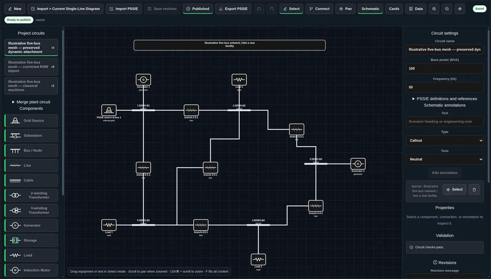
The palette includes grid sources, substations, buses, lines, cables, two- and three-winding transformers, generators, storage, loads, induction motors, shunts, HVDC links, SVCs, STATCOMs, switches, breakers, and disconnectors. See the element and field reference for every field and new-component default.
Connect Equipment
- Select Connect.
- Select a bus or substation.
- Select the equipment to connect to it.
- Repeat for each remaining terminal.
- Select Select to return to editing.
Each connection joins a bus or substation to an equipment terminal. Do not connect two buses directly. Place line, cable, transformer, or switchgear equipment between them. Single-terminal equipment needs one bus. Two-terminal equipment needs two distinct buses. A three-winding transformer needs three distinct buses. An equipment terminal cannot connect twice.
The builder uses the next unused equipment terminal. Check transformer HV, MV, and LV sides after connecting. Each electrical island needs a connected grid source.
Edit and Navigate
| Control | Use |
|---|---|
| Select | Select or drag equipment and annotation text. Select a connection to inspect its endpoints and provenance. |
| Connect | Join bus and equipment terminals. Select the starting item again to cancel that connection. |
| Pan | Drag the background to move around the canvas. |
| Schematic | View electrical symbols, busbars, connections, and annotations. |
| Cards | View equipment cards. |
| Data | Filter by ID, name, or kind. Use All equipment or an equipment type. Edit a row name and its first displayed property. Select the row for the full property editor. |
| Zoom in, Zoom out, Fit circuit to view | Change the view without changing electrical values. |
| Undo, Redo | Undo or redo draft edits. |
| Delete selected | Remove the selected equipment and its connections. Associated callouts are also removed. |
| Remove link | Delete only the selected connection. |
Scroll to pan when zoomed. Hold Ctrl or Command and scroll to zoom. Hold Shift while scrolling for horizontal movement. With canvas focus, use arrow keys to pan, plus or minus to zoom, and F or 0 to fit. Enter or Space selects a focused component, or connects it in Connect mode.
With focus inside the builder, Ctrl/Command+Z undoes an edit. Ctrl/Command+Shift+Z or Ctrl/Command+Y redoes it. Delete or Backspace removes the selection. These shortcuts do not remove equipment while you type in a field.
For a bus or substation, set Busbar orientation to Horizontal, the default, or Vertical. Set Busbar length to change the symbol. The initial length is 120 drawing units; the input range is 20 to 5,000. These are drawing settings, not electrical dimensions. The canvas uses an overview for large or zoomed-out circuits. Use Data and filters to inspect individual records.
Add Notes to the Drawing
- Under Schematic annotations, enter Text.
- Choose Type: Callout, Banner, or Note.
- Choose Tone: Neutral, Healthy, Warning, or Critical.
- Select Add annotation. A callout can attach to the selected equipment with Add annotation to selection.
- Select the annotation to edit Annotation text, Annotation type, Annotation tone, Horizontal position, Vertical position, or Text box width.
- Drag it in Select mode, or use Delete annotation to remove it.
The initial annotation type is Callout and the tone is Neutral. The initial text-box width is 200 drawing units; its input range is 80 to 1,200.
Edit Definitions
Expand PSS/E definitions and references to edit Areas, Zones, Owners, Subsystem definitions, Monitor definitions, and Contingency definitions. Each field must contain a JSON array. Changes apply when the field loses focus. Imported opaque attachments, including DYR data, remain attached to the circuit.
Import a Starting Model
- Import > Current Single-Line Diagram captures the displayed map diagram. Review the preview before creating an unsaved draft.
- Import PSS/E previews model files before Create circuit creates a saved circuit revision.
Save current draft changes before importing or changing circuits. See Network Model Import and Validation for supported files, import diagnostics, and reconciliation.
Check, Save, and Publish
- Read Validation. Correct missing values, invalid ranges, equipment mappings, terminal assignments, and unresolved import issues.
- Review warnings, even when there are no blocking errors.
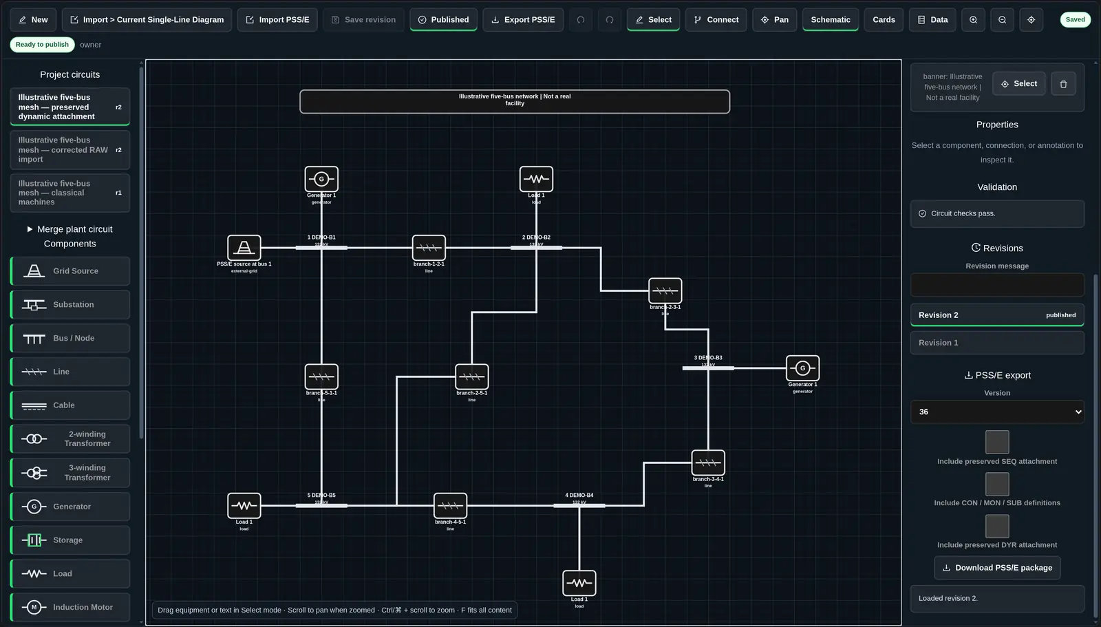
- Enter a Revision message.
- Select Save revision.
- When the saved current revision is Ready to publish, select Publish.
- Wait for Published. The server validates the revision before making it available for studies.
| Status | Meaning and next step |
|---|---|
| Unsaved changes | Edits exist only in the current draft. Save a revision before export or publication. |
| Saved | The current draft matches a stored revision. This does not mean it is published. |
| blocker / blockers | Validation found errors. Correct each error before publishing. |
| Ready to publish | Local blocking checks pass. Save any pending edits, review warnings, then publish. |
| Circuit checks pass. | No local model-validation errors or warnings were found. |
| Published | This revision is the circuit’s published study input. |
Revisions and Concurrent Edits
Project circuits lists the project’s circuits. Revisions lists the selected circuit’s saved versions and identifies the published version.
Historical revisions are read-only. Select Restore as new revision to use an older version as a new draft. Save it to create a new revision without overwriting history.
If another session changes the circuit before you save, your draft is preserved. Select Reload latest to load the new head, or Save draft as copy to preserve your work as a separate circuit. Review pending changes before reloading.
Changing the project or leaving the builder with unsaved changes can require confirmation. Save first if you need to keep the draft.
Use the Published Model
- Select the project in Session Context.
- Open Setup & Run and select a supported study type and engine.
- Select Circuit Revision, then choose Published circuit revision.
- Run Check Readiness before starting the study.
Circuit-revision inputs are available for model quality, power flow, contingency analysis, sensitivity analysis, PTDF/LODF, and cross-check studies. The study uses the selected saved revision, not later edits. Check equipment and method support for the selected study.
For an interchange package, save the revision and use Export PSS/E. The strict circuit export path requires missing electrical values to be supplied before export. See Engineering Exports and Handoffs.
Related Guides
- Grid Circuit Element Reference
- Network Model Import and Validation
- Single-Line Diagrams and Engineering
- Running Engineering Studies
- Engineering Exports and Handoffs


